

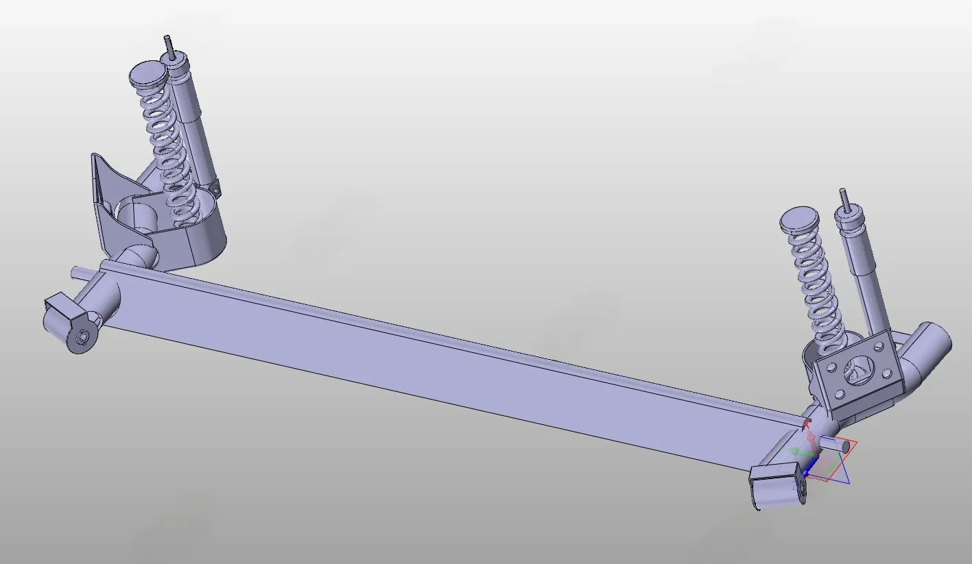
D1433-无人纯电动物流车驱动桥设计【含Catia三维图】 下载积分:100 资料编号: D1433


2.填写金额:100
3.添加备注,填写资料编号:
会有专人在15分钟内把资料发到您邮箱
备注:如果付款忘记填写资料编号,则发邮件时附带您的交易明细截图即可。
请耐心等待,如超过30分钟还没收到,请联系客服QQ:2363701252
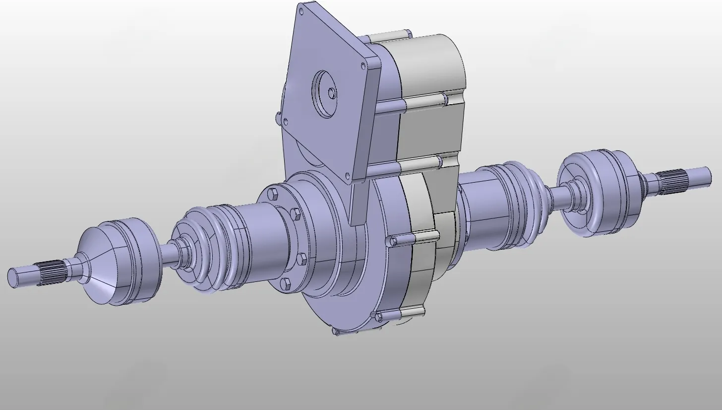
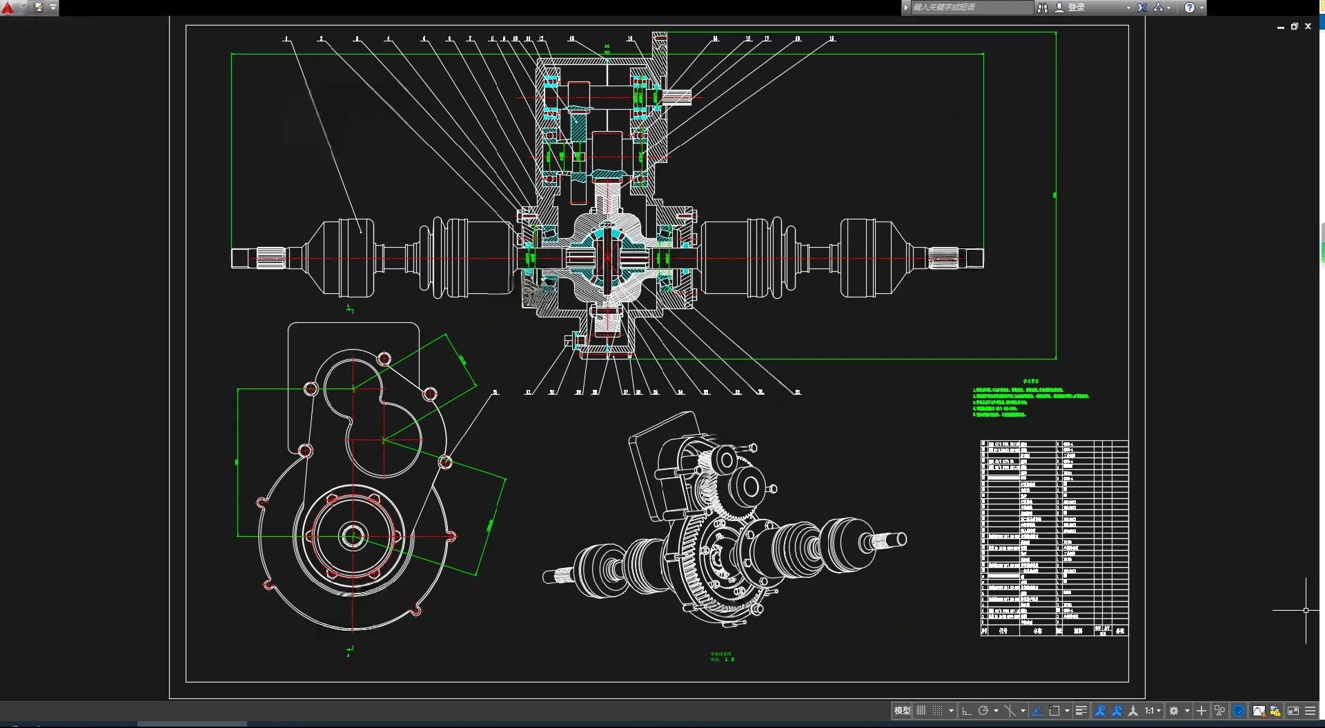
作品描述
作品包括:
Word设计说明书1份,约8000字
任务书一份
开题报告一份
外文翻译一份
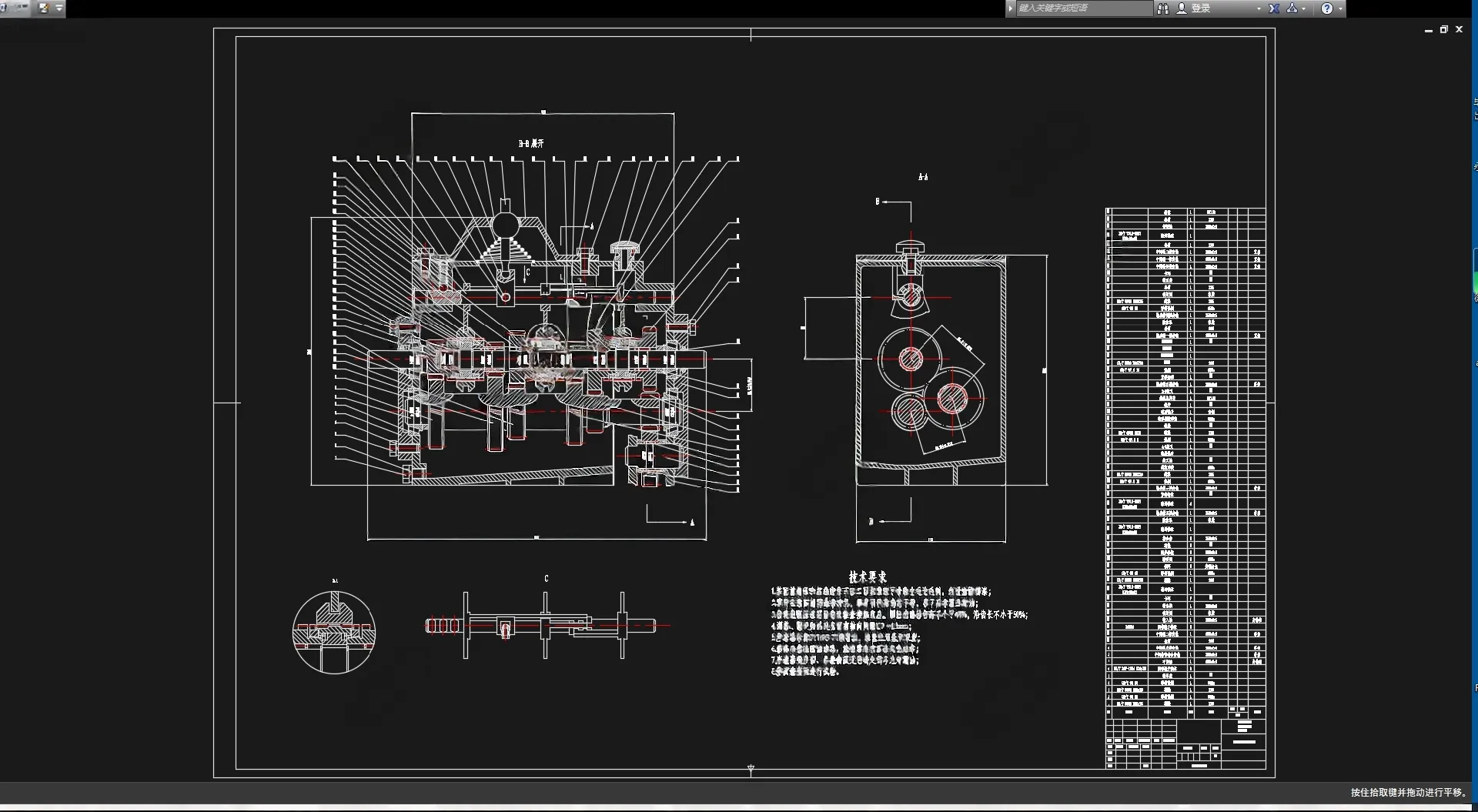
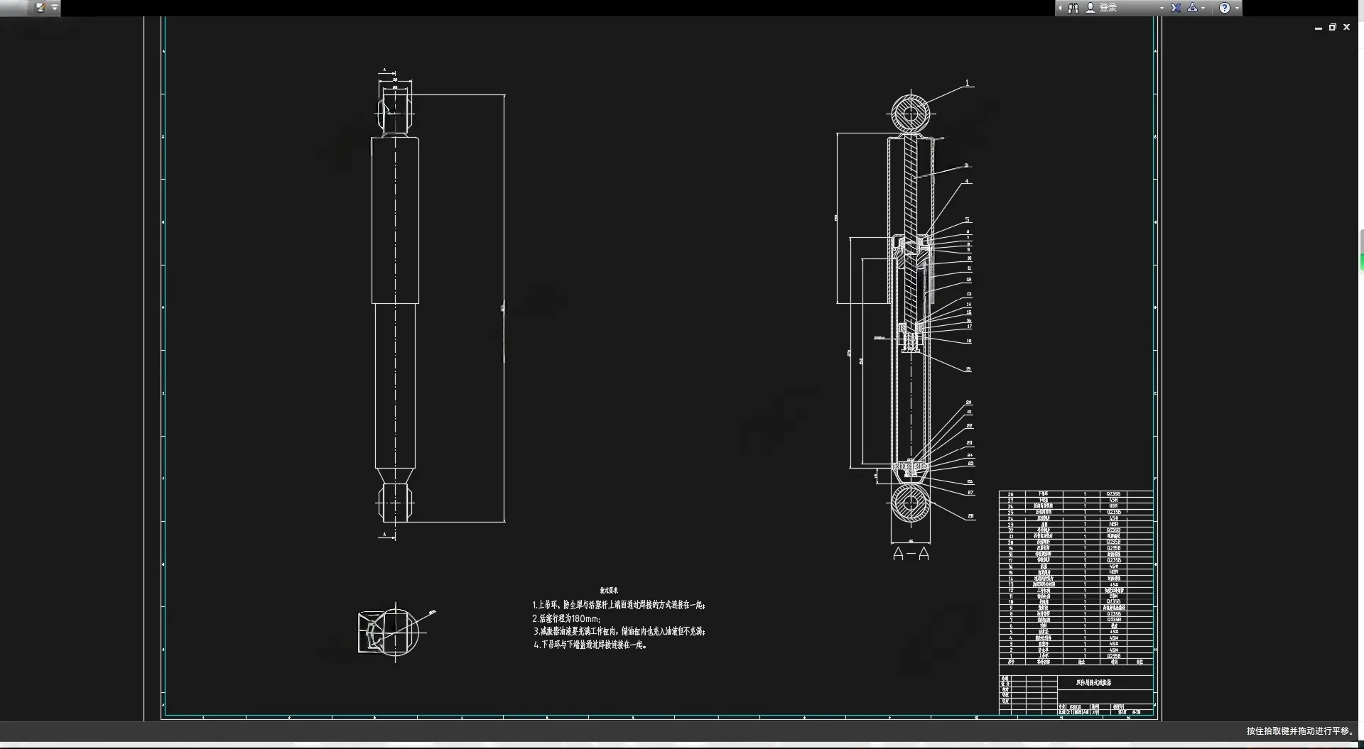
CAD版本图纸,共8张
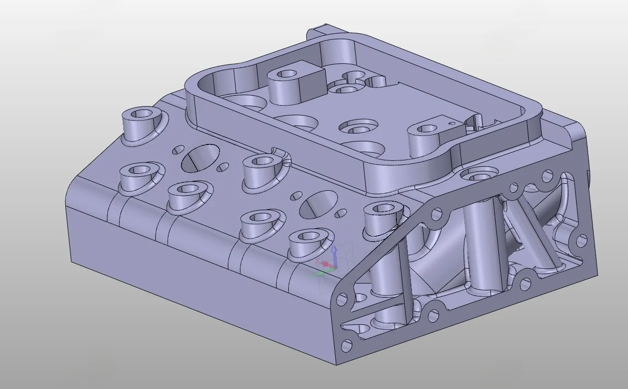
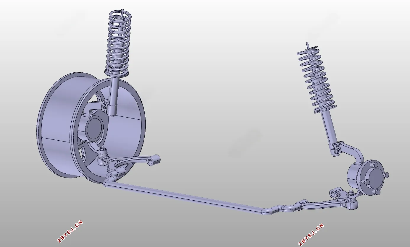
Catia三维图一套

摘要
With the increasing awareness of energy crisis and environmental protection, people pay more attention to pure electric vehicles. Some potential traditional automobile manufacturers at home and abroad often position their products in a high level, so it is difficult to popularize them among majority consumers. As a supplement to middle and high level pure electric vehicles, small and micro pure electric vehicles will reveal a great development potential. This kind of pure electric vehicle has the advantages of compact structure, light weight and low cost.
In this paper, the driving axle of an unmanned electric logistics vehicle based on XinShiQi Company is designed with the help of three-dimensional modeling software CATIA, and finite element analysis software ANSYS. In the design, the characteristics of the drive axle are explained firstly. According to the given data, the structure types and parameters of the final drive, differential, half shaft and universal joint are determined, and the strength is checked. Through calculating the size and referring to the similar parts of the existing vehicle, carry out the 3D model. Then import the model into finite element analysis software to obtain stress nephogram. The results are of great significance to the design and development of the driving axle of the electric logistics vehicle.
Key words: drive axle; electric logistics vehicle; final drive; differential
Contents
Chapter 1 Introduction 1
1.1 The purpose and significance of the research 1
1.2 Overview of research status in China and abroad 2
Chapter 2 Drive axle design 4
2.1 Drive axle type selection 5
2.2 Final drive design 6
2.2.1 Final drive structure technical solution 6
2.2.2 Final drive gear design 8
2.2.3 Strength check of shaft and key 15
2.3 Differential design 20
2.3.1 Main parameters selection of differential gear 20
2.3.2 The material of the differential gear 23
2.3.3 Differential gear geometry calculation 24
2.3.4 Differential gear strength calculation 25
2.4 Half shaft design 26
2.5 Universal joint design 28
2.5.1 Universal joint selection 28
2.5.2 Universal joint size selection 29
Chapter 3 CATIA 3D modeling 31
3.1 Software Introduction 31
3.2 Final drive modeling 31
3.3 Differential Modeling 32
3.4 Drive half shaft modeling 33
3.5 Axle case modeling 34
3.6 Drive axle overall 3D model 34
Chapter 4 ANSYS finite element analysis 36
4.1 Material Settings 36
4.2 Contact and grid settings 36
4.3 Constraints And Loading Settings 37
4.4 Analysis and comparison of results 37
4.5 Summary 39
Chapter 5 Conclusion 40
References 41
Acknowledgement 43
Appendix 44
温馨提示:
1、题目前面的备注【字母数字编号】为本站整理分类的编号,与课题内容无关,请选题时忽视;
2、若题目上备注三维,则表示文件里包含三维源文件,由于三维组成零件数量较多,为保证预览截图的简洁性,本站将三维文件夹进行了打包。三维及CAD预览截图,均为本站电脑打开软件进行截图的,保证能够打开,下载原件超高清,下载后解压即可;
3、本站所有资源如无特殊说明,都需要本地电脑安装Office2007。图纸软件为AutoCAD,PROE,UG,SolidWorks,CATIA等;
4、本站所有图文资料仅供用户学习参考,不作为任何商用或其他用途;
5、本站不保证下载资源的准确性、安全性和完整性, 不包修改,不支持退换,同时也不承担用户因使用这些下载资源对自己和他人造成任何形式的伤害或损失;
6、 下载文件中如有侵权或不适当内容,请与我们联系,我们立即纠正。

线
客
服